- 您现在的位置:买卖IC网 > Sheet目录341 > MAX5037EVKIT (Maxim Integrated Products)EVAL KIT FOR MAX5037
�� �
�
 �
�MAX5037� Evaluation� Kit�
�Detailed� Description�
�The� MAX5037� EV� kit� is� a� voltage-regulating� module� that�
�provides� 1.1V� to� 1.85V� at� 52A� current� from� either� a� 5V� or�
�12V� input.� The� input� voltage� range� can� be� 4.75V� to� 5.5V�
�for� 5V� input� and� 8V� to� 13.2V� for� 12V� input� conditions.�
�Use� 2200μF/16V� across� the� input� if� the� wires� running�
�from� the� source� to� the� EV� kit� are� thin� and� long.� The� out-�
�put� voltage� is� set� from� 5-bit� VID� input� according� to� the�
�Intel� VRM� 9.0� specification� (see� Table� 1).� The� form� factor�
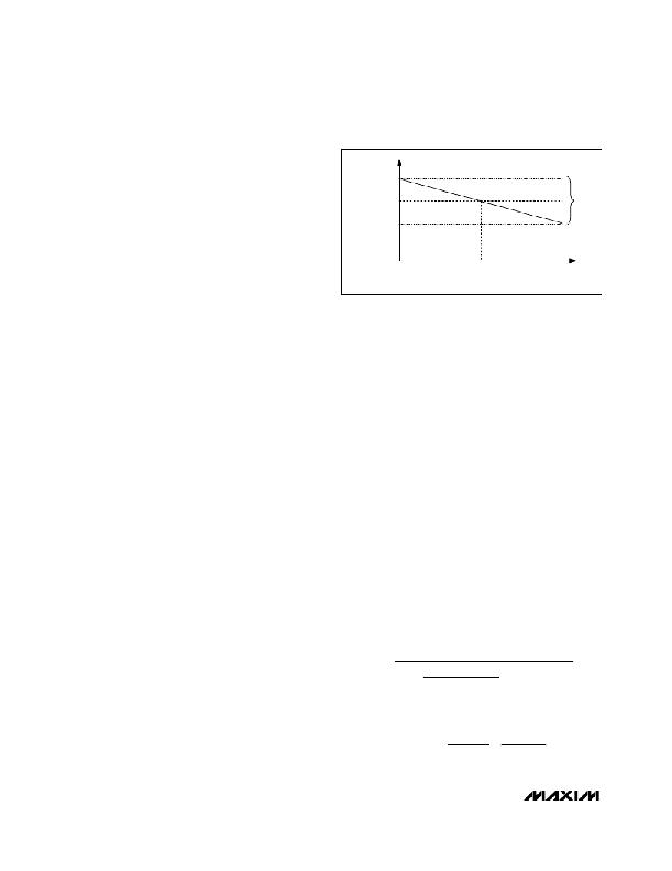
�V� CNTR� +� ?� V� OUT� /2�
�V� CNTR�
�V� CNTR� -� ?� V� OUT� /2�
�and� input/output� terminations� are� also� as� per� the� Intel�
�VRM� 9.0� specification.� See� Table� 2� for� pinouts� of� edge�
�connectors� compatible� with� AMP1364125-1.� CLKIN� is�
�NO� LOAD�
�1/2� LOAD�
�LOAD� (A)�
�FULL� LOAD�
�accessible� through� a� 3-pin� header� (JP3),� and� a� shunt� is�
�provided� for� setting� the� switching� frequency� to� either�
�250kHz� or� 500kHz.� The� phase-shifted� clock� output�
�(CLKOUT)� is� available� at� the� 2-pin� header� (JP5)� and� can�
�be� used� to� synchronize� other� MAX5037� EV� kits.� Use� JP3�
�to� set� the� phase� shift� of� 60� °� ,� 90� °� ,� or� 120� °� .�
�The� MAX5037� EV� kit� is� designed� to� achieve� optimum�
�electrical� performance� at� a� 12V� input.� High� efficiency� is�
�achieved� with� careful� component� selection� (Figure� 18).�
�The� switching� MOSFETs,� inductors,� and� sense� resistors�
�are� the� major� power-dissipating� components.� Two�
�MOSFETs� are� used� at� the� upper� and� lower� sides� of�
�each� phase� to� distribute� the� dissipated� power� in� two�
�different� packages.� The� product� of� the� gate� charge� and�
�on-resistance� of� the� MOSFET� is� a� figure� of� merit,� with� a�
�lower� number� signifying� better� performance.� The�
�MOSFETs� chosen� are� optimized� for� a� high-frequency�
�switching� application.� The� upper� MOSFETs� have� a� low�
�gate� charge� and� moderate� on-resistance,� and� the� lower�
�MOSFETs� have� very� low� on-resistance� and� a� moderate�
�gate� charge.� The� inductor� is� a� low-profile,� high-current�
�type� with� low� DC� resistance.� The� sense� resistors� have�
�very� low� inductance.� Plenty� of� copper� is� provided�
�around� these� power� components� to� dissipate� heat�
�effectively.� The� input� capacitors� are� high-ripple-current�
�capacity,� very� low� ESR,� ceramic� type.� The� output�
�capacitors� have� to� support� large� output� current� during�
�the� load� transient.� Both� polymer� and� ceramic-type�
�capacitors� are� used� to� achieve� high� output� capacitance�
�Figure� 2.� VRM� Loadline� with� V� CNTR� =� VID� at� Half� Load�
�the� shunt� to� pins� 1� and� 2� of� JP4.� For� optimum� transient�
�load� performance,� replace� the� existing� 0.6μH� inductors�
�with� 0.3μH� inductors.�
�Output� Voltage�
�The� output� voltage� set� through� the� VID� code� has� ±0.8%�
�accuracy.� The� voltage� positioning� and� the� ability� to�
�operate� with� multiple� reference� voltages� might� require�
�the� output� to� regulate� away� from� a� center� value.� Define�
�the� center� value� as� the� voltage� when� the� output� voltage�
�equals� the� VID� reference� at� exactly� one-half� the� maximum�
�output� current.�
�Set� the� voltage-positioning� window� (� ?� V� OUT� )� using� the�
�resistive� feedback� of� the� voltage-error� amplifier.� Use�
�the� following� equation� to� determine� the� values� of� R� F�
�(R23)� and� R� IN� (R24)� required� for� setting� the� voltage-�
�positioning� window:�
�?� V� OUT� =� (R24� ?� I� OUT� )� /� (2� ?� R23� ?� G� C� )�
�The� voltage� at� CNTR� (pin� 18)� regulates� to� 1.2V� (Figure�
�18).� The� inverting� input� to� the� voltage-error� amplifier�
�(VEA)� mirrors� the� current� set� by� the� resistor� at� CNTR,�
�centering� the� output� voltage-positioning� window� around�
�the� VID� programmed� output� voltage.� Set� the� center� of�
�the� output� voltage� with� a� resistor� from� CNTR� to� SGND� as:�
�?� +� (� V� OUT� ?� VID� )�
�?� 2� � R� 23� � G� C� ?�
�and low ESR at high frequency.�
�5V� Input� Operation�
�The� EV� kit� is� designed� for� the� best� efficiency,� transient�
�load� performance� at� 12V� input.� The� 5V� input� operation�
�R� 21� =�
�?� R� 24� ?�
�I� OUT� ?�
�1� .� 2� � R� 24�
�can� also� be� verified� without� significant� component�
�change.� Short� the� JMPR-5VIN� pins� with� wire� on� the� bot-�
�tom� layer� of� the� EV� kit� PC� Board.� This� connects� IN� (pin�
�G� C� =�
�0� .� 05�
�R� S�
�28)� and� V� CC� (pin� 27)� of� the� MAX5037.� For� 5V� input�
�operation,� the� switching� frequency� can� be� increased� to�
�500kHz� without� significantly� increasing� the� power� losses.�
�R� S� =�
�R� 1� � R� 2�
�R� 1� +� R� 2�
�=�
�R� 3� � R� 4�
�R� 3� +� R� 4�
�To� change� the� switching� frequency� to� 500kHz,� move�
�6�
�_______________________________________________________________________________________�
�发布紧急采购,3分钟左右您将得到回复。
相关PDF资料
MAX5056AASA+
IC MOSFET DRVR DUAL 8-SOIC
MAX5062AASA+
IC DRIVER HALF BRDG HS 8-SOIC
MAX5075AAUA
IC DRVR FET P-P 8-UMAX
MAX5077AUD+
IC DRVR FET P-P 14-TSSOP
MAX5078BATT+T
IC MOSFET DRIVER 6-TDFN
MAX5092EVKIT+
KIT EVALUATION FOR MAX5092
MAX620EWN
IC DVR QUAD HISIDE MOSFET 18SOIC
MAX626CPA+
IC DRIVER MOSFET DUAL 8-DIP
相关代理商/技术参数
MAX5038
制造商:MAXIM 制造商全称:Maxim Integrated Products 功能描述:Dual-Phase, Parallelable, Average Current-Mode Controllers
MAX5038A
制造商:MAXIM 制造商全称:Maxim Integrated Products 功能描述:Dual-Phase, Parallelable, Average-Current-Mode Controllers
MAX5038AEAI12
功能描述:电流型 PWM 控制器 RoHS:否 制造商:Texas Instruments 开关频率:27 KHz 上升时间: 下降时间: 工作电源电压:6 V to 15 V 工作电源电流:1.5 mA 输出端数量:1 最大工作温度:+ 105 C 安装风格:SMD/SMT 封装 / 箱体:TSSOP-14
MAX5038AEAI12+
制造商:Maxim Integrated Products 功能描述:- Rail/Tube
MAX5038AEAI12-T
功能描述:电流型 PWM 控制器 RoHS:否 制造商:Texas Instruments 开关频率:27 KHz 上升时间: 下降时间: 工作电源电压:6 V to 15 V 工作电源电流:1.5 mA 输出端数量:1 最大工作温度:+ 105 C 安装风格:SMD/SMT 封装 / 箱体:TSSOP-14
MAX5038AEAI15
功能描述:电流型 PWM 控制器 Dual-Phase Parallelable Average RoHS:否 制造商:Texas Instruments 开关频率:27 KHz 上升时间: 下降时间: 工作电源电压:6 V to 15 V 工作电源电流:1.5 mA 输出端数量:1 最大工作温度:+ 105 C 安装风格:SMD/SMT 封装 / 箱体:TSSOP-14
MAX5038AEAI15+
制造商:Maxim Integrated Products 功能描述:- Rail/Tube